It's called a poor man's variac and there are no doubt myriad other websites on this topic. I found some plans for this on Audiokarma.org.
Standard disclaimer: of course you'll need to verify these instructions to make sure everything is safe and sound.
Whereas variacs are variable transformers that limit line voltage to your device under test, the poor man's variac, or dim bulb tester, uses a light bulb to limit current.
The light bulb is wired inline with the electronic device, acting as an inline resistor. But it's better than a simple resistor because light bulb resistance increases when the filament heats up.
When there's no short in the device, some limited current is drawn through the light bulb but not enough to significantly heat the filament so resistance stays relatively low (the device will still see reduced line voltage). But if there's a short in the device it has near zero resistance and wants to draw as much current as possible. The bulb is allowed to light and its resistance climbs, reducing the maximum current that can flow through the damaged equipment.
Hopefully this prevents the magic smoke in your device under test from escaping :)
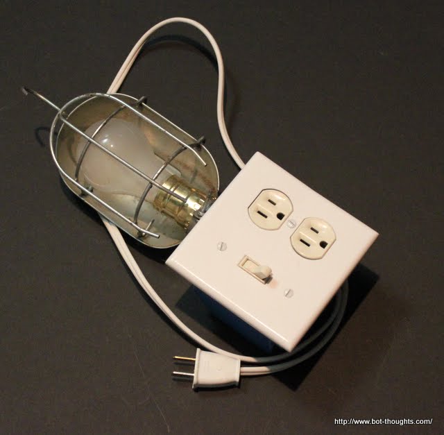
Here are the parts I used to build it
- Lightbulb shield to protect against broken bulb and shocks
- Standard outlet
- Standard switch
- Appropriate gauge household wire: white, black, about 6" each
- A length of lamp cord of appropriate gauge (or use 3-wire cord)
- Polarized plug (or use a grounded plug)
- 2 gang box
- A lamp bulb socket that accepts threaded rod and shield
- Lamp threaded rod and nut hardware
- 40 or 60W bulb (lower wattages allow less current)
Drill a hole in one side of the 2 gang box big enough for the threaded rod. Install this, and clamp to the plastic housing with two nuts. Screw the threaded rod into lamp housing. Install the switch and outlet into the box. Attach the shield around the bulb for safety's sake!!
That is all there is to it! Now plug in your tester and plug a stereo or oscilloscope and flip the switch. The bulb will probably glow brighter at first due to inrush current filling the large capacitors in the power supply and then will grow dim or simply not glow at all if everything is ok. You can start with lower watt bulbs and work your way up to 100W at which point you are probably ok to plug the unit into the wall directly.
Awesome- I am going to build one as we have a larger one that gets a bit heavy carrying around between tech labs.
ReplyDelete